UnityShader3实现2D描边效果
本文实例为大家分享了UnityShader3实现2D描边效果的具体代码,供大家参考,具体内容如下
1.
Shader "Custom/Edge"
{
Properties
{
_MainTex ("Texture", 2D) = "white" {}
_OffsetUV ("OffsetUV", Range(0, 1)) = 0.1
_EdgeColor ("EdgeColor", Color) = (1, 0, 0, 1)
_AlphaTreshold ("Treshold", Range(0, 1)) = 0.5
}
SubShader
{
Tags { "Queue" = "Transparent" }
Blend SrcAlpha OneMinusSrcAlpha
Pass
{
CGPROGRAM
#pragma vertex vert
#pragma fragment frag
#include "UnityCG.cginc"
struct appdata
{
float4 vertex : POSITION;
fixed2 uv : TEXCOORD0;
};
struct v2f
{
float4 vertex : SV_POSITION;
fixed2 uv[5] : TEXCOORD0;
};
sampler2D _MainTex;
float4 _MainTex_ST;
fixed _OffsetUV;
fixed4 _EdgeColor;
fixed _AlphaTreshold;
v2f vert (appdata v)
{
v2f o;
o.vertex = mul(UNITY_MATRIX_MVP, v.vertex);
o.uv[0] = v.uv;
o.uv[1] = v.uv + fixed2(0, _OffsetUV); //up
o.uv[2] = v.uv + fixed2(-_OffsetUV, 0); //left
o.uv[3] = v.uv + fixed2(0, -_OffsetUV); //bottom
o.uv[4] = v.uv + fixed2(_OffsetUV, 0); //right
return o;
}
fixed4 frag (v2f i) : SV_Target
{
fixed4 original = tex2D(_MainTex, i.uv[0]);
fixed alpha = original.a;
fixed p1 = tex2D(_MainTex, i.uv[1]).a;
fixed p2 = tex2D(_MainTex, i.uv[2]).a;
fixed p3 = tex2D(_MainTex, i.uv[3]).a;
fixed p4 = tex2D(_MainTex, i.uv[4]).a;
alpha = p1 + p2 + p3 + p4 + alpha;
alpha /= 5;
if (alpha < _AlphaTreshold) original.rgb = _EdgeColor.rgb;
return original;
}
ENDCG
}
}
}
2.
Shader "Custom/Edge"
{
Properties
{
_Edge ("Edge", Range(0, 0.2)) = 0.043
_EdgeColor ("EdgeColor", Color) = (1, 1, 1, 1)
_MainTex ("MainTex", 2D) = "white" {}
}
SubShader
{
Pass
{
CGPROGRAM
#pragma vertex vert
#pragma fragment frag
#include "UnityCG.cginc"
fixed _Edge;
fixed4 _EdgeColor;
sampler2D _MainTex;
struct appdata
{
float4 vertex : POSITION;
fixed2 uv : TEXCOORD0;
};
struct v2f
{
float4 vertex : SV_POSITION;
float4 objVertex : TEXCOORD0;
fixed2 uv : TEXCOORD1;
};
v2f vert (appdata v)
{
v2f o;
o.vertex = mul(UNITY_MATRIX_MVP, v.vertex);
o.objVertex = v.vertex;
o.uv = v.uv;
return o;
}
fixed4 frag (v2f i) : SV_Target
{
fixed x = i.uv.x;
fixed y = i.uv.y;
if((x < _Edge) || (abs(1 - x) < _Edge) || (y < _Edge) || (abs(1 - y) < _Edge))
{
return _EdgeColor * abs(cos(_Time.y));
}
else
{
fixed4 color = tex2D(_MainTex, i.uv);
return color;
}
//return i.objVertex;
//return fixed4(i.uv, 0, 1);
}
ENDCG
}
}
}
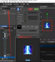
3.如下图,左边是一个Image,右边是一个Plane。
// Upgrade NOTE: replaced 'mul(UNITY_MATRIX_MVP,*)' with 'UnityObjectToClipPos(*)'
Shader "Custom/Edge"
{
Properties
{
_Edge ("Edge", Range(0, 0.2)) = 0.043
_EdgeColor ("EdgeColor", Color) = (1, 1, 1, 1)
_FlowColor ("FlowColor", Color) = (1, 1, 1, 1)
_FlowSpeed ("FlowSpeed", Range(0, 10)) = 3
_MainTex ("MainTex", 2D) = "white" {}
}
SubShader
{
Tags { "Queue"="Transparent" "RenderType"="Transparent" "IgnoreProjector"="True" }
Pass
{
ZWrite Off
Blend SrcAlpha OneMinusSrcAlpha
CGPROGRAM
#pragma vertex vert
#pragma fragment frag
#include "UnityCG.cginc"
fixed _Edge;
fixed4 _EdgeColor;
fixed4 _FlowColor;
float _FlowSpeed;
sampler2D _MainTex;
struct appdata
{
float4 vertex : POSITION;
fixed2 uv : TEXCOORD0;
};
struct v2f
{
float4 vertex : SV_POSITION;
fixed2 uv : TEXCOORD1;
};
v2f vert (appdata v)
{
v2f o;
o.vertex = UnityObjectToClipPos(v.vertex);
o.uv = v.uv;
return o;
}
fixed4 frag (v2f i) : SV_Target
{
fixed x = i.uv.x;
fixed y = i.uv.y;
if((x < _Edge) || (abs(1 - x) < _Edge) || (y < _Edge) || (abs(1 - y) < _Edge))
{
//点旋转公式:
//假设对图片上任意点(x,y),绕一个坐标点(rx0,ry0)逆时针旋转a角度后的新的坐标设为(x0,y0),有公式:
//x0 = (x - rx0) * cos(a) - (y - ry0) * sin(a) + rx0 ;
//y0 = (x - rx0) * sin(a) + (y - ry0) * cos(a) + ry0 ;
float a = _Time.y * _FlowSpeed;
float2 rotUV;
x -= 0.5;
y -= 0.5;
rotUV.x = x * cos(a) - y * sin(a) + 0.5;
rotUV.y = x * sin(a) + y * cos(a) + 0.5;
fixed temp = saturate(rotUV.x - 0.5);//-0.5作用是调整流动颜色的比例
return _EdgeColor * (1 - temp) + _FlowColor * temp;
}
else
{
//fixed4 color = tex2D(_MainTex, i.uv);
return fixed4(1, 1, 1, 0);
}
}
ENDCG
}
}
}
4.通过观察上面的效果图,会发现右边的Plane出现了锯齿。而解决锯齿一般的方法就是做模糊处理,模糊处理一般又有贴图处理和代码处理之分,这里使用的是贴图处理。贴图处理需要提供一张边界模糊的贴图。
如上图,左下是内边反锯齿的图,右上是未经处理的图。
// Upgrade NOTE: replaced 'mul(UNITY_MATRIX_MVP,*)' with 'UnityObjectToClipPos(*)'
Shader "Custom/Edge2"
{
Properties
{
_Edge ("Edge", Range(0, 0.2)) = 0.043
_EdgeColor ("EdgeColor", Color) = (1, 1, 1, 1)
_FlowColor ("FlowColor", Color) = (1, 1, 1, 1)
_FlowSpeed ("FlowSpeed", Range(0, 10)) = 3
_MainTex ("MainTex", 2D) = "white" {}
}
SubShader
{
Tags { "Queue"="Transparent" "RenderType"="Transparent" "IgnoreProjector"="True" }
Pass
{
ZWrite Off
Blend SrcAlpha OneMinusSrcAlpha
CGPROGRAM
#pragma vertex vert
#pragma fragment frag
#include "UnityCG.cginc"
fixed _Edge;
fixed4 _EdgeColor;
fixed4 _FlowColor;
float _FlowSpeed;
sampler2D _MainTex;
struct appdata
{
float4 vertex : POSITION;
fixed2 uv : TEXCOORD0;
};
struct v2f
{
float4 vertex : SV_POSITION;
fixed2 uv : TEXCOORD1;
};
v2f vert (appdata v)
{
v2f o;
o.vertex = UnityObjectToClipPos(v.vertex);
o.uv = v.uv;
return o;
}
fixed4 frag (v2f i) : SV_Target
{
fixed4 color = tex2D(_MainTex, i.uv);
float alpha = color.a;
fixed x = i.uv.x;
fixed y = i.uv.y;
float a = _Time.y * _FlowSpeed;
float2 rotUV;
x -= 0.5;
y -= 0.5;
rotUV.x = x * cos(a) - y * sin(a) + 0.5;
rotUV.y = x * sin(a) + y * cos(a) + 0.5;
fixed temp = saturate(rotUV.x - 0.5);//-0.5作用是调整流动颜色的比例
fixed4 finalColor = _EdgeColor * (1 - temp) + _FlowColor * temp;
finalColor.a = alpha;
return finalColor;
}
ENDCG
}
}
}
以上是 UnityShader3实现2D描边效果 的全部内容, 来源链接: utcz.com/z/312780.html


