Getting Started Tutorial--How to Explore the Camera Vulnerability (Firmware)
Author: fenix@Knownsec 404 Team
Date: November 27, 2017
Chinese Version: https://paper.seebug.org/649/
0x00 Introduction
According to Gartner, an IT research and consulting firm, the number of IoT devices worldwide will reach 8.4 billion in 2017, up 31% from 6.4 billion in 2016, while the global population is 7.5 billion. The number of IoT devices will reach 20.4 billion in 2020.
In response, the security issues of IoT are also increasingly prominent, especially for common devices such as webcams and routers. The rapid growth in the number of IoT devices is in sharp contrast to the serious lag in their security. At the same time, it also provides new opportunity for malicious attackers and security researchers to play the game of good versus evil on a new battlefield.
This is a detailed introductory level tutorial for many enthusiasts who want to get started with smart device security.
0x01 Overview
1.0 Firmware and Its Common Access Methods
Firmware is a program written in EROM (Erasable Read Only Memory) or EEPROM(Electrically Erasable Programmable Read Only Memory). In particular, for most routers and cameras on the market, the firmware is the program in the 25 series Flash chip on the board, which houses the embedded operating system, usually a Linux system.
Obtaining the firmware is the premise of analyzing and mining firmware vulnerabilities. This paper will take the camera as an example to show how to dump firmware in Flash chips and some bright ideas after obtaining the firmware.
In general, there are several ways to obtain firmware.
From the official: The firmware of devices such as routers and cameras can usually be downloaded directly from the official, while it doesn’t support firmware download for most other IoT devices. The official generally only provide the latest firmware, not conducive to the study of historical firmware vulnerabilities.
Grab packet to analyze the download address of firmware: When the phone controller (APP) can upgrade the firmware, you can try this method to obtain the firmware. If the firmware is upgraded in the form of patches, the complete firmware cannot be obtained, and data encryption may be difficult to crack.
Obtain via the serial port: Get shell from the debug serial port, then package and upload system files.
Read the firmware memory chip directly: It is the simplest and most direct way to read the firmware memory chip directly through the programmer. If there is line interference, which can only be read offline, the equipment may be damaged during welding.
This paper deals with the latter two ways to extract firmware.
0x02 About the Concepts
Before starting the formal firmware extraction, we need to grasp several basic concepts.
The Serial Port and UART
The serial port is mainly used for serial bit-by-bit data transmission.
The serial port asynchronously transmits and receives bytes in bits following the UART protocol. Normally, three pairs of pins need to be connected, and the connection mode is as follows:

(Image via Internet)
In the figure above, TX is the receiving end, RX is the transmission end, and GND is the ground end. Connect the debug serial port of the board and the USB to TTL serial cable as shown. After setting important parameters such as baud rate, data bit, stop bit and parity check, the two sides can send ASCII characters normally, so as to carry out asynchronous serial communication.
2.1 u-boot
U-boot is a kind of boot program commonly used in embedded system. It is executed before the operating system runs, to initialize the hardware and software environment, and finally to boot the system kernel.
0x03 Enter the System through the Debug Serial Port
3.0 Research Objects
In this section, we will start with a wireless surveillance camera and explain how to get the Shell of the system through the debug serial port.

Detect the open port and service of the camera by using nmap, and the result is as follows:
Host is up (0.0031s latency).Not shown: 996 closed ports
PORT STATE SERVICE VERSION
100/tcp open http Mongoose httpd
554/tcp open rtsp
1935/tcp open tcpwrapped
100100/tcp open soap gSOAP 2.8
Mongoose monitoring on port 100 is an embedded Web server, and gSOAP is a cross-platform tool for developing Web Service servers and clients. RTSP (Real Time Streaming Protocol) is an application-layer protocol in TCP/IP protocol system, which defines how one-to-many applications can effectively transmit multimedia data over IP networks.
The packet analysis of services can then be done by using tools like Fidder, wireshark, and others, but that's not the focus of this paper. Next we will analyze from the perspective of hardware.
3.1 Tools
- USB to TTL serial cable
- soldering iron
- screwdrivers
- …
3.2 Where is UART
Manufacturers of routers, cameras and other equipment usually leave debug serial ports on the devices to facilitate development or after-sales debugging. In order to communicate with the equipment, we first need to find these "backdoors". Disassemble camera apart with tools, and identify the purpose of the chip according to the model on the motherboard. As shown in the figure, we found the location of the processor and memory chip. The processor is GK7102, and the memory chip is IC25LP128. There are three free interfaces on the motherboard in the right picture. After testing, the lower left one is the 4-pin debug serial port (baud rate 115200), the first pin of the serial port is Tx, the third pin is Rx, respectively connected with the Rx and Tx of USB-to-TTL. The line and the motherboard are powered by the same Hub, and the VCC is not much different, and no GND is connected.

As for how to find the debug serial port on the device, you can refer to reverse-engineer-serial ports, no more details here.
minicom is a serial port tool on the Linux platform. Type the following command at the console to communicate with the serial port.
# Use the following Bash code:minicom -D /dev/ttyUSB0
You can use the following way in case of the permissions issues in this step.
sudo chmod 777 /dev/ttyUSB03.3 Startup Process of Embedded System
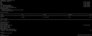
The laptop is properly connected to the motherboard serial port. After power supply, the following debugging information during system startup can be seen in the terminal.


The partition information of Flash chip is as follows:

After booting up, the system starts the following services, which may be the main process of the camera service.

After the system is started, the Shell login interface is provided.

By observing the startup process, we have gained a lot of useful information and have a general understanding of how u-boot boots the system.
Finally, we tried to use weak passwords to get the Shell of the system. Unfortunately, after many attempts, we failed.
3.4 Login Bypass
If you've ever used Linux, maybe you've experienced the awkwardness of forgetting your system password and not being able to access it. Our solution is very simple and direct: go directly to the grub boot to change the password. Therefore, if the device is within reach, there is almost no problem of access to the system.
On a camera running an embedded Linux operating system, there exists u-boot as well, similar to grub.
Restart the device and enter the u-boot command line by typing the combination keys.
There are many built-in commands for us to use in the u-boot command line. Type “h” to view the help.

Print the parameter information passed to the kernel by u-boot via printenv.

The contents of some of the parameters show how u-boot transfers control to the kernel.
- Firstly, set the startup parameters for the kernel.
console=${consoledev},${baudrate} noinitrd mem=${mem} rw ${rootfstype} init=linuxrc
Load the kernel from Flash into memory.
Jump to the starting address of the kernel in memory and execute.
Let's focus on the init field of the startup parameter.
The init field sets the name of the initialization process executed by the kernel, such as linuxrc above, which is a piece of program code located in the root directory of the file system, responsible for subsequent system initialization.
Is it possible to directly modify init=/bin/sh to access the root file system when the system is not initialized? Modify the init field in sfboot as /bin/sh in the u-boot command line and save as follows (make a backup of parameters before modification):
console=${consoledev},${baudrate} noinitrd mem=${mem} rw ${rootfstype} init=/bin/shRestarting the device, as we suspected, modifying the initial process of kernel execution, we successfully obtained a shell.

Since there is no linuxrc initialization process, the Shell functionality is greatly limited. Edit the /etc/shadow file under the shell, erase or crack the root user's password, restart to the u-boot command line interface, modify the original boot parameters and save, restart to the shell login interface again, and you can get a shell with complete functions.
3.5 Package and Upload Firmware
Based on the previous steps, We can now log into a fully functional Shell and use tar and tftp commands to pack and upload the root file system to the tftp server.
3.6 Other Tricks
The relevant commands are provided in u-boot to operate the Flash chip, so the firmware can also be extracted as follows (the way of cat memory is just an idea, speed is a great limitation).

0x04 Simply Reading and Writing Firmware Storage Chip Unlock New Features
In this section, we take another camera based on gSOAP protocol as an example (firmware memory chip MX25LP128) to show how to use a programmer to read and write Flash chips to open the Telnet service of the camera.
4.0 Tools
- 25 Series Chip Programmer
- soldering iron
- …
4.1 Reading Firmware
MX25L128 is a 25 series Flash chip that can read directly online. Clamp the Flash chip and connect the programmer to read the firmware inside.

Click SmartID, and then click on Read after the chip model is successfully identified, and save it as a file. As shown below, the reading process is very smooth.

4.2 Firmware Decompression
Binwalk is a firmware analysis tool developed by @devttys0. It is highly recommended to use the tutorial installation on Github. Installing apt-get directly will lack many dependencies.
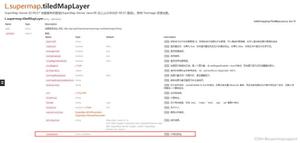
View the firmware structure using binwalk.

After compiling (make), the kernel generates two files, one is Image and the other one is zImage. Image is the kernel image file and the zImage is an image compression file of the kernel.
As for uImage, it is an image file dedicated to u-boot. It adds a 64-byte header in front of zImage to indicate the kernel version, loading location, generation time, size and other information. After 0x40, there is no difference with zImage.
The firmware uses the squashfs file system, a set of GPL open source read-only compressed file systems for the Linux kernel. Therefore, the firmware cannot be modified when the device is running normally. In the previous section, the reason why we entered the system through the serial port by modifying the initial process of the kernel is that the system has not been initialized and we gained read and write rights to the file system.
In the latter part of the firmware, there is an area that can be written. A JFFS2 file system, which is a very widely used read/write file system on flash memory. Modified configuration information and other data during device operation will be written to this file system.
The squashfs file system starts at 0x3800000 and is 6963644 bytes in size. Extract the file system with the dd command and decompress it with the unsquashfs command.

4.3 Unlock the New Function
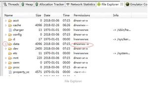
Be familiar with file system structure and existing commands.

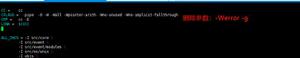
Obviously, the firmware Shell is based on busybox. From the result of file instruction, we can judge that the camera is a 32-bit ARM instruction architecture.
This busybox is statically linked and does not rely on other library files. You can use qemu-arm directly to simulate the running.

Of course, we can also build a qemu virtual machine.
Download qemu virtual machine image file and launch the virtual machine as follows.

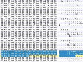
Now we can determine that the telnetd command exists on the target file system. Add the following content at the end of the boot.sh file in the root directory to enable the device to automatically start the Telnet service on startup.

4.4 Reseal
Having finished the simple modification of the file system, so how do we repackage the firmware so that it can flash back to the device?
Start with the firmware structure again as follows:

What we customize is only the middle part of the file system, which is the 0x3100000 - 0xB00000. At the same time, the length of this segment is not equal to the size of the squashfs file system, which is 6963644 bytes. There is a 0xff padding portion from the end of the squashfs file system to the beginning of the next segment.

As can be seen from the uImage header, the image size is 2217456, while the squashfs file system starts at 3670016. There is no CRC check for the squashfs file system.
Judging from the above conclusions, we only need to repackage the modified file system into firmware without changing the original firmware structure.


Connect each segment with cat.
![]()
4.5 Brush Back
We've finished the repackage. Use the programmer to brush the modified firmware offline into the firmware memory chip.
4.6 Outcome
As you can see, we successfully turned on the telnet service for this camera.

0x05 Conclusion
A good understanding of the hardware and software of smart devices is the basis for exploring the device vulnerabilities. This paper is a summary of some experience in the research process of camera and other IoT devices, and I wish it’s helpful.
About Knownsec & 404 Team
Beijing Knownsec Information Technology Co., Ltd. was established by a group of high-profile international security experts. It has over a hundred frontier security talents nationwide as the core security research team to provide long-term internationally advanced network security solutions for the government and enterprises.
Knownsec's specialties include network attack and defense integrated technologies and product R&D under new situations. It provides visualization solutions that meet the world-class security technology standards and enhances the security monitoring, alarm and defense abilities of customer networks with its industry-leading capabilities in cloud computing and big data processing. The company's technical strength is spanly recognized by the State Ministry of Public Security, the Central Government Procurement Center, the Ministry of Industry and Information Technology (MIIT), China National Vulnerability Database of Information Security (CNNVD), the Central Bank, the Hong Kong Jockey Club, Microsoft, Zhejiang Satellite TV and other well-known clients.
404 Team, the core security team of Knownsec, is dedicated to the research of security vulnerability and offensive and defensive technology in the fields of Web, IoT, industrial control, blockchain, etc. 404 team has submitted vulnerability research to many well-known vendors such as Microsoft, Apple, Adobe, Tencent, Alibaba, Baidu, etc. And has received a high reputation in the industry.
The most well-known sharing of Knownsec 404 Team includes: KCon Hacking Conference, Seebug Vulnerability Database and ZoomEye Cyberspace Search Engine.
以上是 Getting Started Tutorial--How to Explore the Camera Vulnerability (Firmware) 的全部内容, 来源链接: utcz.com/p/199394.html